


BASIC METAL CUTTING THEORY- CUTTING TOOLS- terminology- tool materials
Work shop Technology For Engineering & Diploma
BASIC METAL CUTTING THEORY
The usual conception of cutting suggests clearing the substance apart with a thin knife or wedge. When metal is cut the action is rather different and although the tool will always be wedge-shaped in the cutting area and the cutting edge should always be sharp the wedge angle will be far too great for it to be considered knife-shaped. Consequently, a shearing action takes place when the work moves.
a tool being moved against a fixed workpiece. When the cut is in progress the chip presses heavily on the top face of the tool and continuous shearing takes place across the shear plane AB. Although the Figure shows a tool working in the horizontal plane with the workpiece stationary, the same action takes place with the workpiece revolving and the tool stationary.
MACHINE TOOL:
A machine tool may be defined as a power-driven machine that accomplishes the cutting or machining operations on it. The fundamental machine tools that are used for most of the machining processes are lathe, drilling, tapping, shaping, milling and grinding machines.
CUTTING TOOLS
There are basically two types of cutting tools:
- Single point (e.g. turning tools).
- Multiple points (e.g. milling tools).
In general Single Point Cutting Tool is used which is made of H S S(high-speed steel). The main alloying elements in H S S are l8-4-l (i.e.; l8% Tungsten, 4% chromium and l% vanadium, it has 0.75% carbon and l2% cobalt).
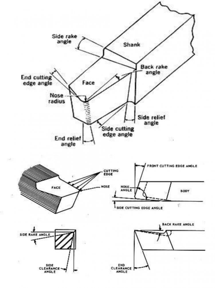
The terminology of the single-point cutting tool.
Shank: The shank is the portion of the tool bit which is not ground to form cutting edges and is rectangular in cross-section.
Face: The face of the cutting tool is that surface against which the chip slides upward.
Flank: The lank of a cutting tool is that surface that faces the work piece.
Heel: The heel of a single point tool is the lowest portion of the side cutting edges.
Nose: The nose of a tool is the conjunction of the side-and end-cutting edges. A nose radius increases the tool life and improves the surface finish.
Base: The base of a tool is the underside of the shank.
Rake: The rake is the slope of the top away from the cutting edge. The larger the rake angle, the larger the shear angle and subsequently the cutting force and power reduction.
End cutting edge angle: It is the angle between the face of the tool and a plane perpendicular to the side of the shank. It varies from 5 to l5 degrees.
The actual geometry varies with the type of work to be done. The standard cutting tool shapes are shown in figure 3.
- Facing tools are ground to provide clearance with a centre.
- Roughing tools have a small side relief angle to leave more material to support the cutting edge during deep cuts.
- Finishing tools have a more rounded nose to provide a finer finish. Round nose tools are for lighter turning. They have no back or side rake to permit cutting in either direction.
- Left-hand cutting tools are designed to cut best when travelling from left to right.
- Aluminium is cut best by specially shaped cutting tools (not shown) that are used with the cutting edge slightly above the centre to reduce chatter.
TOOL ANGLES
There are three important angles in the construction of a cutting tool rake angle, clearance angle and plan approach angle.
Rake Angle
Rake angle is the angle between the top face of the tool and the normal to the work surface at the cutting edge. In general, the larger the rake angle, the smaller the cutting force on the tool. A large rake angle will improve cutting action but would lead to early tool failure since the tool wedge angle is relatively weak. A compromise must therefore be made between adequate strength and good cutting action.
Clearance Angle
Clearance angle is the angle between the flank or front face of the tool and a tangent to the work surface originating at the cutting edge. All cutting tools must have clearance to allow cutting to take place. Clearance should be kept to a minimum, as excessive clearance angle will not improve cutting efficiency and will merely weaken the tool. The typical value for the front clearance angle is 6° in external turning.
TOOL MATERIALS IN COMMON USE
The different materials used for cutting tools are:
|
1. |
High carbon steel |
5. |
Cemented carbides |
|
2. Alloy steels |
6. |
Ceramics |
|
|
3. |
High-speed steel |
7. |
Diamonds |
|
4. Satellites |
8. |
Abrasives |
|
High Carbon Steel: Contains 1 - 1.4% carbon with some addition of chromium and tungsten to improve wear resistance. The steel begins to lose its hardness at about 250° C and is not favoured for modern machining operations where high speeds and heavy cuts are usually employed.
High-Speed Steel (H.S.S.): Steel, which has a hot hardness value of about 600° C, possesses good strength and shock-resistant properties. It is commonly used for single-point lathe cutting tools and multi-point cutting tools such as drills, reamers and milling cutters.
Cemented Carbides: An extremely hard material made from tungsten powder. Carbide tools are usually used in the form of brazed or clamped tips. High cutting speeds may be used and materials difficult to cut with HSS may be readily machined using the carbide-tipped tool.
What's Your Reaction?